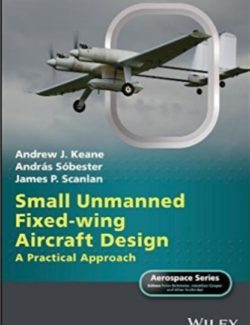
[PDF] Small Unmanned Fixed Wing Aircraft Design: A Practical Approach - Andrew J. Keane, András Sóbester, James P. Scanlan - 1st Edition

Small Unmanned Fixed-Wing Aircraft Design – Andrew J. Keane, András Sóbester, James P. Scanlan – 1st Edition

Descripción

Los vehículos aéreos no tripulados (a veces vehículos aéreos no tripulados o incluso sistemas, UAV o UAS) se están volviendo cada vez más comunes en todo el mundo. Originalmente reservados a organizaciones militares muy secretas, ahora son utilizados de forma rutinaria por equipos de filmación, granjeros, equipos de búsqueda y rescate, aficionados, etc. Se han superado la mayoría de las dificultades tecnológicas para construir un sistema que pueda iniciar, despegar, cumplir una misión y regresar sin intervención humana, y la adopción más amplia de estas tecnologías ahora es principalmente una cuestión de costo, aceptación pública y aprobación regulatoria.

Los únicos desafíos tecnológicos restantes se refieren esencialmente al grado de autonomía a bordo y la toma de decisiones que pueden proporcionar estos vehículos. Si se pueden mantener comunicaciones seguras y sólidas con un piloto en tierra para proporcionar capacidades de toma de decisiones, se pueden lograr misiones muy ambiciosas con bastante facilidad. La toma de decisiones a bordo está menos avanzada, pero los desarrollos continúan a buen ritmo. Los orígenes de nuestro interés en los UAV provienen de los muchos años que hemos pasado en el negocio del diseño, tanto práctico como académico, docente e investigador. Esto nos ha expuesto a una gran cantidad de actividad relacionada en los sectores aeroespacial y marino, cuyos procesos han cambiado considerablemente a lo largo del tiempo que hemos estado involucrados.

Un tema recurrente ha sido la rápida evolución en el conjunto de herramientas de software utilizado para ayudar a los diseñadores, y es en esta área en la que nos hemos comprometido principalmente. Para nuestros puntos de vista, es central una forma de ver el diseño de ingeniería que distingue entre síntesis (el negocio de generar descripciones nuevas o modificadas de artefactos) y análisis (donde uno usa las leyes de la física, los experimentos y la experiencia pasada para evaluar la probable o real desempeño del artefacto diseñado). Es por el uso del análisis formal y la experimentación para atribuir valor a un artefacto que el diseño de ingeniería se distingue de otras formas de diseño.

Por lo tanto, para ser útiles en el mundo del diseño de ingeniería, las herramientas deben ayudar a describir el producto o proceso que se está diseñando, analizarlo o respaldar la entrega e integración de estos procesos, todo lo demás es solo burocracia: el diseño siempre debe verse como un proceso de toma de decisiones. En este libro nos enfocamos en un aspecto particular del área de rápido crecimiento de la tecnología UAV: el diseño, construcción y operación de UAV de ala fija de bajo costo en la clase de peso máximo de despegue (MTOW) de 2 a 150 kg que se encuentran a bajas velocidades subsónicas. Dichos vehículos pueden ofrecer plataformas robustas de larga duración capaces de operar durante 10 horas o más con presupuestos muy por debajo de $100 000, a menudo menos de $10 000. Pueden transportar cargas útiles significativas y operar desde instalaciones terrestres relativamente simples. A continuación, se expone un enfoque para el diseño y la construcción de estos vehículos aéreos no tripulados, desarrollado durante muchos años en la Universidad de Southampton. Si bien existen, sin duda, muchas otras formas válidas de producir vehículos aéreos no tripulados, la que se describe aquí funciona para nosotros, proporcionando plataformas efectivas de bajo costo para la enseñanza, la investigación y la explotación comercial.
Ver más
  • List of Figures
    List of Tables
    Foreword
    Series Preface
    Preface
    Acknowledgments

    PART I INTRODUCING FIXED-WING UAVS
    1 Preliminaries
    1.1 Externally Sourced Components
    1.2 Manufacturing Methods
    1.3 Project DECODE
    1.4 The Stages of Design
    1.4.1 Concept Design
    1.4.2 Preliminary Design
    1.4.3 Detail Design
    1.4.4 Manufacturing Design
    1.4.5 In-service Design and Decommissioning
    1.5 Summary
    2 Unmanned Air Vehicles
    2.1 A Brief Taxonomy of UAVs
    2.2 The Morphology of a UAV
    2.2.1 Lifting Surfaces
    2.2.2 Control Surfaces
    2.2.3 Fuselage and Internal Structure
    2.2.4 Propulsion Systems
    2.2.5 Fuel Tanks
    2.2.6 Control Systems
    2.2.7 Payloads
    2.2.8 Take-off and Landing Gear
    2.3 Main Design Drivers

    PART II THE AIRCRAFT IN MORE DETAIL
    3 Wings
    3.1 Simple Wing Theory and Aerodynamic Shape
    3.2 Spars
    3.3 Covers
    3.4 Ribs
    3.5 Fuselage Attachments
    3.6 Ailerons/Roll Control
    3.7 Flaps
    3.8 Wing Tips
    3.9 Wing-housed Retractable Undercarriage
    3.10 Integral Fuel Tanks
    4 Fuselages and Tails (Empennage)
    4.1 Main Fuselage/Nacelle Structure
    4.2 Wing Attachment
    4.3 Engine and Motor Mountings
    4.4 Avionics Trays
    4.5 Payloads – Camera Mountings
    4.6 Integral Fuel Tanks
    4.7 Assembly Mechanisms and Access Hatches
    4.8 Undercarriage Attachment
    4.9 Tails (Empennage)
    5 Propulsion
    5.1 Liquid-Fueled IC Engines
    5.1.1 Glow-plug IC Engines
    5.1.2 Spark Ignition Gasoline IC Engines
    5.1.3 IC Engine Testing
    5.2 Rare-earth Brushless Electric Motors
    5.3 Propellers
    5.4 Engine/Motor Control
    5.5 Fuel Systems
    5.6 Batteries and Generators
    6 Airframe Avionics and Systems
    6.1 Primary Control Transmitter and Receivers
    6.2 Avionics Power Supplies
    6.3 Servos
    6.4 Wiring, Buses, and Boards
    6.5 Autopilots
    6.6 Payload Communications Systems
    6.7 Ancillaries
    6.8 Resilience and Redundancy
    7 Undercarriages
    7.1 Wheels
    7.2 Suspension
    7.3 Steering
    7.4 Retractable Systems
    PART III DESIGNING UAVS
    8 The Process of Design
    8.1 Goals and Constraints
    8.2 Airworthiness
    8.3 Likely Failure Modes
    8.3.1 Aerodynamic and Stability Failure
    8.3.2 Structural Failure
    8.3.3 Engine/Motor Failure
    8.3.4 Control System Failure
    8.4 Systems Engineering
    8.4.1 Work-breakdown Structure
    8.4.2 Interface Deinitions
    8.4.3 Allocation of Responsibility
    8.4.4 Requirements Flowdown
    8.4.5 Compliance Testing
    8.4.6 Cost and Weight Management
    8.4.7 Design “Checklist”
    9 Tool Selection
    9.1 Geometry/CAD Codes
    9.2 Concept Design
    9.3 Operational Simulation and Mission Planning
    9.4 Aerodynamic and Structural Analysis Codes
    9.5 Design and Decision Viewing
    9.6 Supporting Databases
    10 Concept Design: Initial Constraint Analysis
    10.1 The Design Brief
    10.1.1 Drawing up a Good Design Brief
    10.1.2 Environment and Mission
    10.1.3 Constraints
    10.2 Airframe Topology
    10.2.1 Unmanned versus Manned – Rethinking Topology
    10.2.2 Searching the Space of Topologies
    10.2.3 Systematic “invention” of UAV Concepts
    10.2.4 Managing the Concept Design Process
    10.3 Airframe and Powerplant Scaling via Constraint Analysis
    10.3.1 The Role of Constraint Analysis
    10.3.2 The Impact of Customer Requirements
    10.3.3 Concept Constraint Analysis – A Proposed Computational Implementation
    10.3.4 The Constraint Space
    10.4 A Parametric Constraint Analysis Report
    10.4.1 About This Document
    10.4.2 Design Brief
    10.4.3 Unit Conversions
    10.4.4 Basic Geometry and Initial Guesses
    10.4.5 Preamble
    10.4.6 Preliminary Calculations
    10.4.7 Constraints
    10.5 The Combined Constraint Diagram and Its Place in the Design Process
    11 Spreadsheet-Based Concept Design and Examples
    11.1 Concept Design Algorithm
    11.2 Range
    11.3 Structural Loading Calculations
    11.4 Weight and CoG Estimation
    11.5 Longitudinal Stability
    11.6 Powering and Propeller Sizing
    11.7 Resulting Design: Decode-1
    11.8 A Bigger Single Engine Design: Decode-2
    11.9 A Twin Tractor Design: SPOTTER
    12 Preliminary Geometry Design
    12.1 Preliminary Airframe Geometry and CAD
    12.2 Designing Decode-1 with AirCONICS
    13 Preliminary Aerodynamic and Stability Analysis
    13.1 Panel Method Solvers – XFoil and XFLR5
    13.2 RANS Solvers – Fluent
    13.2.1 Meshing, Turbulence Model Choice, and y+
    13.3 Example Two-dimensional Airfoil Analysis
    13.4 Example Three-dimensional Airfoil Analysis
    13.5 3D Models of Simple Wings
    13.6 Example Airframe Aerodynamics
    13.6.1 Analyzing Decode-1 with XFLR5: Aerodynamics
    13.6.2 Analyzing Decode-1 with XFLR5: Control Surfaces
    13.6.3 Analyzing Decode-1 with XFLR5: Stability
    13.6.4 Flight Simulators
    13.6.5 Analyzing Decode-1 with Fluent
    14 Preliminary Structural Analysis
    14.1 Structural Modeling Using AirCONICS
    14.2 Structural Analysis Using Simple Beam Theory
    14.3 Finite Element Analysis (FEA)
    14.3.1 FEA Model Preparation
    14.3.2 FEA Complete Spar and Boom Model
    14.3.3 FEA Analysis of 3D Printed and Fiber- or Mylar-clad Foam Parts
    14.4 Structural Dynamics and Aeroelasticity
    14.4.1 Estimating Wing Divergence, Control Reversal, and Flutter Onset Speeds
    14.5 Summary of Preliminary Structural Analysis
    15 Weight and Center of Gravity Control
    15.1 Weight Control
    15.2 Longitudinal Center of Gravity Control
    16 Experimental Testing and Validation
    16.1 Wind Tunnels Tests
    16.1.1 Mounting the Model
    16.1.2 Calibrating the Test
    16.1.3 Blockage Effects
    16.1.4 Typical Results
    16.2 Airframe Load Tests
    16.2.1 Structural Test Instruments
    16.2.2 Structural Mounting and Loading
    16.2.3 Static Structural Testing
    16.2.4 Dynamic Structural Testing
    16.3 Avionics Testing
    17 Detail Design: Constructing Explicit Design Geometry
    17.1 The Generation of Geometry
    17.2 Fuselage
    17.3 An Example UAV Assembly
    17.3.1 Hand Sketches
    17.3.2 Master Sketches
    17.4 3D Printed Parts
    17.4.1 Decode-1: The Development of a Parametric Geometry for the SLS Nylon Wing Spar/Boom “Scaffold Clamp”
    17.4.2 Approach
    17.4.3 Inputs
    17.4.4 Breakdown of Part
    17.4.5 Parametric Capability
    17.4.6 More Detailed Model
    17.4.7 Manufacture
    17.5 Wings 3
    17.5.1 Wing Section Proile
    17.5.2 Three-dimensional Wing
    PART IV MANUFACTURE AND FLIGHT
    18 Manufacture
    18.1 Externally Sourced Components
    18.2 Three-Dimensional Printing
    18.2.1 Selective Laser Sintering (SLS)
    18.2.2 Fused Deposition Modeling (FDM)
    18.2.3 Sealing Components
    18.3 Hot-wire Foam Cutting
    18.3.1 Fiber and Mylar Foam Cladding
    18.4 Laser Cutting
    18.5 Wiring Looms
    18.6 Assembly Mechanisms
    18.6.1 Bayonets and Locking Pins
    18.6.2 Clamps
    18.6.3 Conventional Bolts and Screws
    18.7 Storage and Transport Cases
    19 Regulatory Approval and Documentation
    19.1 Aviation Authority Requirements
    19.2 System Description
    19.2.1 Airframe
    19.2.2 Performance
    19.2.3 Avionics and Ground Control System
    19.2.4 Acceptance Flight Data
    19.3 Operations Manual
    19.3.1 Organization, Team Roles, and Communications
    19.3.2 Brief Technical Description
    19.3.3 Operating Limits, Conditions, and Control
    19.3.4 Operational Area and Flight Plans
    19.3.5 Operational and Emergency Procedures
    19.3.6 Maintenance Schedule
    19.4 Safety Case
    19.4.1 Risk Assessment Process
    19.4.2 Failure Modes and Effects
    19.4.3 Operational Hazards
    19.4.4 Accident List
    19.4.5 Mitigation List
    19.4.6 Accident Sequences and Mitigation
    19.5 Flight Planning Manual
    20 Test Flights and Maintenance
    20.1 Test Flight Planning
    20.1.1 Exploration of Flight Envelope
    20.1.2 Ranking of Flight Tests by Risk
    20.1.3 Instrumentation and Recording of Flight Test Data
    20.1.4 Pre-light Inspection and Checklists
    20.1.5 Atmospheric Conditions
    20.1.6 Incident and Crash Contingency Planning, Post Crash Safety, Recording, and Management of Crash Site
    20.2 Test Flight Examples
    20.2.1 UAS Performance Flight Test (MANUAL Mode)
    20.2.2 UAS CoG Flight Test (MANUAL Mode)
    20.2.3 Fuel Consumption Tests
    20.2.4 Engine Failure, Idle, and Throttle Change Tests
    20.2.5 Autonomous Flight Control
    20.2.6 Auto-Takeoff Test
    20.2.7 Auto-Landing Test
    20.2.8 Operational and Safety Flight Scenarios
    20.3 Maintenance
    20.3.1 Overall Airframe Maintenance
    20.3.2 Time and Flight Expired Items
    20.3.3 Batteries
    20.3.4 Flight Control Software
    20.3.5 Maintenance Record Keeping
    21 Lessons Learned
    21.1 Things that Have Gone Wrong and Why
    PART V APPENDICES, BIBLIOGRAPHY, AND INDEX
    A Generic Aircraft Design Flowchart
    B Example AirCONICS Code for Decode-1
    C Worked (Manned Aircraft) Detail Design Example
    C.1 Stage 1: Concept Sketches
    C.2 Stage 2: Part Deinition
    C.3 Stage 3: “Flying Surfaces”
    C.4 Stage 4: Other Items
    C.5 Stage 5: Detail Deinition
    Bibliography
    Index
  • Citar Libro

Descargar Small Unmanned Fixed Wing Aircraft Design: A Practical Approach

Tipo de Archivo
Idioma
Descargar RAR
Descargar PDF
Páginas
Tamaño
Libro
Inglés
468 pag.
16 mb

Déjanos un comentario

No hay comentarios

guest
0 Comentarios
Comentarios en línea
Ver todos los comentarios
0
Nos encantaría conocer tu opinión, comenta.x